Memory Recall Training System
An Embedded Game for Cognitive and Reaction Speed Enhancement
Author: Ioana-Alexia DEACONU
GitHub Project Link: https://github.com/UPB-PMRust-Students/project-alexiadeaconu
Description
Memory Recall Training System is a microcontroller-based interactive game that challenges players to enhance their short-term memory and reaction speed. It works by generating and displaying sequences of LED activations which the player must reproduce correctly using buttons. The system dynamically adjusts its behavior based on selected difficulty levels and provides real-time audio-visual feedback via a buzzer and LCD. At the end of each game, the system displays the final score, calculated based on accuracy and reaction time, and sends the result to an online leaderboard via Wi-Fi.
Motivation
This project was chosen due to its potential to combine several embedded systems topics: hardware control (LEDs, buttons, PWM for sound), real-time input processing, user interface via an LCD, and network communication. Moreover, the cognitive aspect of the game provides a meaningful and engaging application of embedded technology in educational or therapeutic contexts.
Architecture
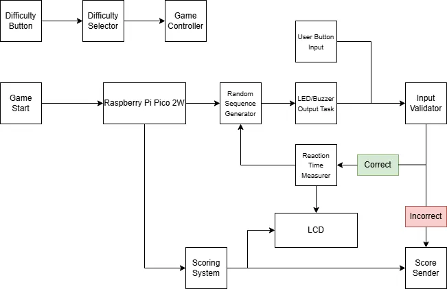
1. Difficulty Button
- Function: User input to select game difficulty.
- Behavior: Cycles through Easy, Medium, Hard.
2. Difficulty Selector
- Function: Reads the state of the Difficulty Button.
- Behavior: Maintains the currently selected difficulty level.
- Interaction: Informs the Game Controller to adjust sequence logic and scoring weights.
3. Game Controller
- Function: Central unit managing the game logic.
- Responsibilities:
- Starts game when initiated.
- Coordinates sequence generation, input validation, and score calculation.
4. Random Sequence Generator
- Function: Generates a random sequence of LED combinations.
- Tool: Uses the rand crate.
- Output: Passes the generated sequence to the Output Task.
5. Output Task (LEDs + Buzzer)
- Function: Provides visual and audio feedback.
- Behavior:
- Activates LEDs in a predefined sequence.
- Plays distinct tones for each LED using the buzzer.
6. User Button Input
- Function: Allows user to replicate the LED sequence.
- Behavior: Captures physical button presses and passes them to the Input Validator.
7. Input Validator
- Function: Compares the player's input to the original generated sequence.
- Logic:
- Correct input: trigger Reaction Time Measurer and continue game.
- Incorrect input: end game and trigger Scoring System.
8. Reaction Time Measurer
- Function: Measures the player's response time.
- Tool: Uses embassy-time timers.
- Output: Reaction time data used in scoring.
9. Scoring System
- Function: Calculates the player's final score.
- Criteria:
- Input accuracy
- Reaction time
- Difficulty level
10. LCD Display
- Function: Displays game state and results.
- Tool: Uses hd44780-driver.
- Content:
- Current difficulty
- Reaction times
- Final score
11. Score Sender
- Function: Sends final score to leaderboard.
- Tools: embassy-net, reqwest, serde
- Behavior:
- Converts score to JSON
- Sends via POST request to server
Log
Week 5 - 11 May
Week 12 - 18 May
Week 19 - 25 May
Hardware
The project uses the Raspberry Pi Pico 2W as the main microcontroller, powered via USB and programmed using a Raspberry Pi Debug Probe over the SWD interface. Key hardware components include:
-
LEDs (Red, Yellow, Green, Blue): Connected to GPIO pins via 220Ω resistors to limit current.
-
Push Buttons: 6 buttons connected to GPIO pins.
-
Passive Buzzer: Connected to a PWM-capable GPIO pin for audio tone output.
-
1602 LCD Module: Wired in 4-bit parallel mode, using six GPIOs for control and data.
-
Breadboards (830 points): Used to prototype the circuit layout.
-
Male-to-Male Jumper Wires: For connecting components to the breadboard and microcontroller.
-
Power Distribution: 3.3V and GND from the Pico are shared across the breadboard rails.
All components are integrated onto the breadboard to form a compact and testable embedded system.
Schematics
Place your KiCAD schematics here.
Bill of Materials
| Device | Usage | Price |
|---|---|---|
| Raspberry Pi Pico 2W | The microcontroller | 39.66 RON |
| Debug Probe | Programming & debugging | 69.06 RON |
| LCD Module 1602 Backlight Yellow Green 5V | Display | 9.82 RON |
| LEDs | Visual indicators | 4 x 0.39 RON |
| Resistors 0.25W 220Ω | LED current limiting | 4 x 0.10 RON |
| Push Buttons | User input | 6 x 1.99 RON |
| Passive Buzzer | Audio feedback | 0.99 RON |
| Breadboard HQ (830 points) | Prototyping connections | 2 x 9.98 RON |
| Male-to-Male Jumper Wires | For wiring components | 7.99 RON |
Software
| Library | Description | Usage |
|---|---|---|
| embassy-rs | Asynchronous embedded framework | Core async runtime and I/O handling |
| embassy-executor | Task scheduling and execution framework for embedded systems | Used for managing asynchronous tasks with Spawner |
| embassy-rp | Raspberry Pi Pico 2W hardware abstraction | Used for controlling GPIO pins, PWM, and peripherals |
| embassy-net | Network stack | Used for HTTP POST score submission |
| embassy-sync | Synchronization primitives for async code | Provides Mutex for protecting shared resources in async tasks |
| embassy-time | Time handling for asynchronous applications | Used for managing timers and delays (Duration, Timer, Instant) |
| hd44780-driver | LCD driver | Control of the LCD |
| heapless | Fixed-size strings | Efficient string manipulation without heap |
| rand | Random number generation library | LED sequence generation |
| reqwest | HTTP client library | HTTP requests (POST for score submission) |
| serde | Serialization/deserialization framework | Used for serializing and deserializing data (JSON for network communication) |
| defmt | Efficient embedded logging framework | Debug output and panic diagnostics |
| panic-probe | Minimal panic handler for embedded systems | Handles panic situations and logs output via defmt |